

 (203) 753-2114
  (203) 756-5489
Rotary Broaching FAQs
- What is rotary broaching?
- How does rotary broaching work?
- What materials, coolant and coating do you recommend for broaching?
- What speeds & feeds should I be running at?
- What is the best way to center the broach?
- How should I prepare the hole to be broached?
- Is there anything I should know about the broaching tool itself?
- Is there any way to align features such as a cross-hole or a flat with a broached feature?
- Troubleshooting Common Broaching Issues
What is rotary broaching?
Rotary broaching is the process by which a non-round shape is produced on either the inside or outside of a part. Somma Tool offers hex broaches, square broaches, and hexalobe broaches, as well as custom sizes and forms.| Video 1: Rotary Broaching |
 |
| Video 2: Internal and External Rotary Broaching |
| Video 3: Vertical Broaching (CNC Mill) |
How does rotary broaching work?
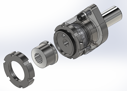
Rotary broaching works because the head of the broaching holder is offset from the centerline of the shank on a 1° angle (see Video 1). This creates a shearing effect around the edges of the form being cut – essentially only a section of the form is being cut at any given time – which greatly reduces the amount of cutting pressure needed to form the desired feature.The rotary broach holder has a spindle which spins independently of the rest of the holder. Thus, if you are rotary broaching on a lathe or screw machine, when the broach tool meets the rotating part, it begins spinning at the same rate as the part (see Video 2).
If you are rotary broaching on a mill or rotary transfer machine, the rotating broach and holder are fed towards a stationary part. In this case, when the broach tool meets the part, it will stop spinning (see Video 3).
What materials, coolant and coating do you recommend for broaching?
Somma Tool recommends making the broaches out of Forte high speed steel. It has the best cost effectiveness and is resistant to chipping.However, for tougher materials such as stainless or hardened steels or exotics, we would recommend making the broach out of T15 due to its better wear resistance compared to Forte.
If possible, broaching should be done with an oil-based coolant. This will provide more lubricity to the broaching process and could extend the tool life by as much as 2-3 times. If you can’t use oil, a high-concentration water-soluble coolant is acceptable. 100% synthetic is not recommended and will result in poor tool life.
For most common materials a TiN coating will help the broach. TiN is also recommended if you are running 100% synthetic coolant as it will make up some of the lost lubricity.
TiCN will help when machining aluminum, cast iron or brass. TiAlN is recommended for broaching 1144 or nickel.
Alcrona is the best for machining Inconel, titanium, and stainless steels such as 416 or 17-4.
What speeds & feeds should I be running at?
The bearings on the smaller broach tool holders (8mm shank broaches) are designed to run at speeds up to 3400 RPM. The bearings on the larger broach tool holders (½” & ¾” shank broaches) are designed to run at speeds between 800-1200 RPM.The following are the recommended feed rate ranges for common hex broaches & square broaches:
| Across-Flat Dimension |
Hex (IPR) | Square (IPR) |
| 1/8 | .001/.002 | .001/.002 |
| 1/4 | .002/.004 | .002/.004 |
| 3/8 | .003/.005 | .003/.005 |
| 1/2 | .004/.006 | .003/.005 |
| 5/8 | .005/.007 | .004/.006 |
| 3/4 | .005/.006 | .004/.006 |
| 7/8 | .004/.005 | .002/.004 |
| 1" | .002/.004 | .001/.003 |
On the other hand, in softer materials such as aluminum, too slow of a feed rate could create a counterboring effect if the broach cannot properly grab into the material. For these materials, you should go no lower than a feed rate of .004 IPR.
What is the best way to center the broach?
You measure the across-point or OD of the broach to be used and install the broach into the holder. Then install the holder into the machine. In a piece of scrap stock, drill and ream a hole to .001 larger than the previously measured across-point dimension.
Next, loosen the two cap screws on the holder so that the body separates from the shank by about 3/16”. Bring the broach head manually to within .030 of the hole and slide the broach into the hole. Continue jogging the turret towards the hole until the broach head is no longer separated from the shank.
Finally, tighten up the two cap screws while making sure that the broach and spindle can still rotate freely. This method will get you on center within approximately a .002 runout.
How should I prepare the hole to be broached?
|
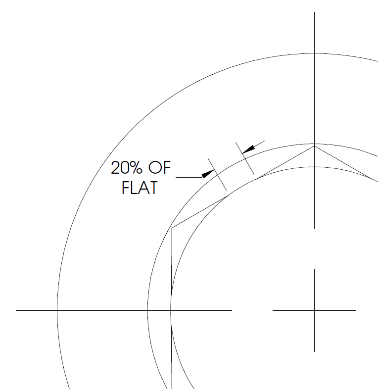
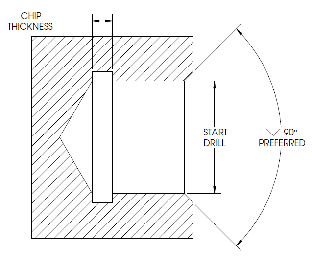
If you’re not bound by any print specs, we recommend drilling the hole out up to a 33% witness mark. This will lessen the cutting force needed to broach. The formula to calculate the start drill based on this is 1.0184 x A/F for hex broaches and 1.0541 x A/F for squares.
There should also be a 90° countersink at the start of the hole that is greater than the across-point or OD of the broach. This is absolutely necessary. If your print does not allow for the countersink, you can make the part longer and face off the countersink after the broaching process.
You can also put a recess at the bottom of the hole – again, greater than the across-point or OD. This is optional; however it will help the chips to clear out of the hole without having to go back in to drill them out after the broaching process.
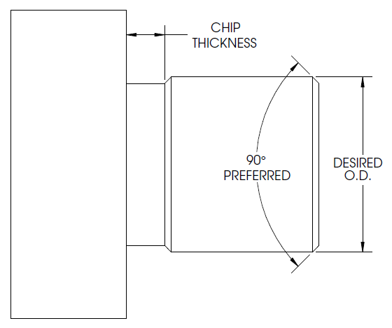
For external forms, there are no ANSI-type standards. However, we do recommend turning the OD of the bar to below the across-point or to the OD of a non-polygonal broach. This will reduce the cutting pressure necessary by creating multiple chips.
There should be a 90° point to lower than the ID of the feature at the start of the feature to be broached. Again, this can be faced off afterwards if it’s not allowable per the print.
Turning an optional recess smaller than the ID at the end of the broached feature will also help in clearing chips from the workpiece.
Is there anything I should know about the broaching tool itself?
There are a few common features on every broaching tool.First, every broach tool has a draft angle. This is ground or cut to be slightly greater than the 1° tilt of the holder to provide clearance in case the machine or tool isn’t perfectly on center.
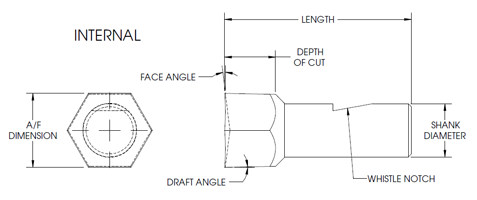
Internal Hex Broach
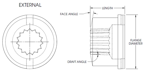
External Spline Broach
 Each broach tool also has a face angle. These create a sharper cutting edge on the broach face and can vary on the broaches for different materials.
 Internal broaches are located on their shank and held in place by a set screw clamped onto a whistle notch. External broaches are located on their outer flange and held in place by a spindle cap and drive pin.
Is there any way to align features such as a cross-hole or a flat with a broached feature?
Yes, there is. On vertical applications, you can install a special attachment onto the non-rotating part of the tool spindle as shown in this video:
Troubleshooting Common Broaching Issues
The broach is “counterboring” the part instead of producing the form I want.
Counterboring is caused primarily in softer materials such as aluminum where the broach cannot grab the material and therefore does not rotate at the same speed as the material. There are a few ways to remedy this.
- Loosen the bearings in the holder
- If possible, you can broach .005-.010 into the part with the spindle stopped and then start rotating the workpiece or holder
- Increase the feed rate to .004 IPR minimum
The broach form is “spiraling” down the length of cut.
Spiraling is caused by misalignment between the broach and the work spindle. In an ideal world, the broach would be driven by the leading edge of the hole. However, due to the draft angle on the broach, the slight space that occurs could cause the broach to slip – especially on long cuts. There are a few ways to remedy this.
- If you believe your machine is rigid enough, the draft angle can be ground to exactly 1° instead of slightly more.
- You can reverse the spindle back and forth throughout the cut – although this will only create spiraling in the other direction giving you a somewhat straighter hole
- In some thin-walled applications, we’ve found that rotating the spindle in the opposite direction from which the start hole was drilled prevents spiraling.
- A driven broach holder will eliminate spiraling completely.
My machine isn’t powerful enough to broach a keyway form.
Keyways larger than 1/8” wide are one of the toughest forms to broach because of the large chip being taken out without the benefit of a start hole. If you are unable to pre-drill or mill the keyway so that the broach is only essentially taking out the corners, the best way to broach the part is on a machine that can be indexed. Install the broach directly into a collet in the turret (not in a rotary holder) and lock the machine spindle. Then “chisel” away at the form by indexing into the keyway in .005-.010 increments.
Another thing to keep in mind is that it will be less expensive to do this with a standard square broach with an across-flat dimension equal to the width of the keyway, rather than a specially formed keyway broach.
 |
Visit Our YouTube Channel at youtube.com/sommatool for Broaching Videos and More |